

How To Make A Wireless Doorbell Circuit Using A 433 MHz RF Transceiver Circuit Diagram

Best Multimeter for Work on Ship Circuit Diagram
Best Multimeter for Work on Ship Circuit Diagram Other safety features, like internal blast shields,
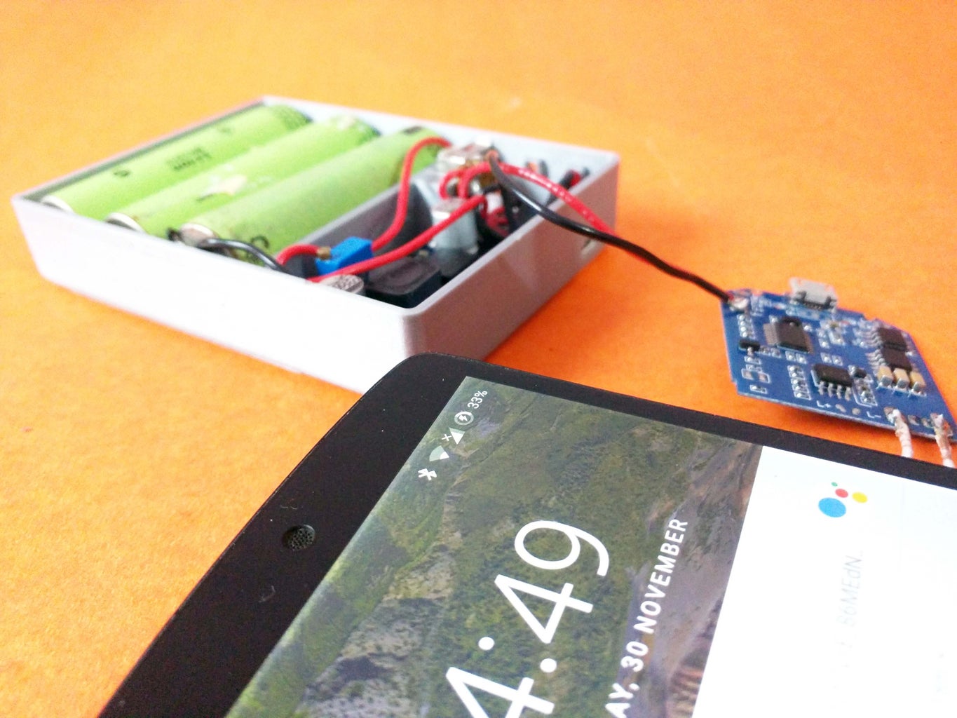
DIY Wireless Charging Power Bank 8 Steps with Pictures Circuit Diagram
DIY Wireless Charging Power Bank 8 Steps with Pictures Circuit Diagram For this Power bank,
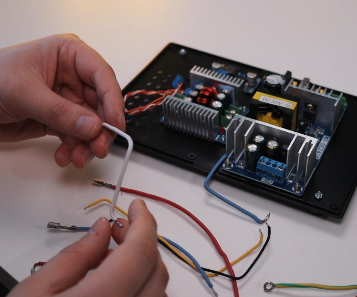
DIY Lab Bench Power Supply Build Tests 16 Steps with Pictures Circuit Diagram
DIY Lab Bench Power Supply Build Tests 16 Steps with Pictures Circuit Diagram In this

the circuit diagram for an active low pass filter
the circuit diagram for an active low pass filter Active Low Pass Filter Circuit Diagram.

Reflow Soldering VS Wave Soldering Whats the difference Circuit Diagram
Reflow Soldering VS Wave Soldering Whats the difference Circuit Diagram On the other hand, industrial
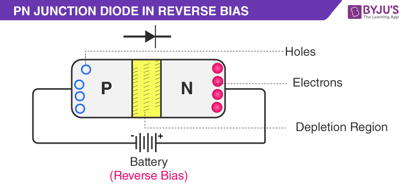
Uses of diode With Its Applications in Practical World Circuit Diagram
Uses of diode With Its Applications in Practical World Circuit Diagram In the devices you

How to Make a Laser Communicator to Solar Cell Circuit Diagram
How to Make a Laser Communicator to Solar Cell Circuit Diagram Laser is used in

Towards the Internet of Smart Trains A Circuit Diagram
Towards the Internet of Smart Trains A Circuit Diagram By embracing an integrated rail ecosystem

DIY Temperature based fan Circuit Diagram
DIY Temperature based fan Circuit Diagram The fan speed is controlled by using PWM signals.

Exploring AI with the Raspberry Pi Circuit Diagram
Exploring AI with the Raspberry Pi Circuit Diagram Next we come to the actual electronics

Hydroponics Garden Plants Monitoring for Arduino Circuit Diagram
Hydroponics Garden Plants Monitoring for Arduino Circuit Diagram With the help of Arduino, sensors, and

Figure 4 from RFID Based Toll Collection System Circuit Diagram
Figure 4 from RFID Based Toll Collection System Circuit Diagram Hey Friends In This Video

Testing Electronic Components Circuit Diagram
Testing Electronic Components Circuit Diagram Learn how to use a multimeter to measure continuity, resistance,

Electronic Circuit Design Guidelines Wiring Core Circuit Diagram
Electronic Circuit Design Guidelines Wiring Core Circuit Diagram The best electronic circuit design practices include

Demonstration of robotic arm control A Overview of a central Circuit Diagram
Demonstration of robotic arm control A Overview of a central Circuit Diagram Complete guide on
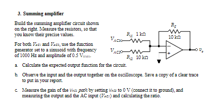
Solved 1 To study operational amplifier op amp and its Circuit Diagram
Solved 1 To study operational amplifier op amp and its Circuit Diagram Figure 7 shows

4 Ways to Read Schematics Circuit Diagram
4 Ways to Read Schematics Circuit Diagram Schematic diagrams are like road maps of electronic

Membuat RFID Door Control Dengan Arduino Circuit Diagram
Membuat RFID Door Control Dengan Arduino Circuit Diagram Learn how to make Arduino RFID/NFC Door

Overvoltage Protection Circuit Circuit Diagram
Overvoltage Protection Circuit Circuit Diagram So, we comprehended that both the higher voltages and the